CS61C项目笔记(四)-proj3-构建CPU流水线
今天是 24·10·21 日,时隔 1 个月重新开始完成 proj3 这个大项目,该项目主要是构建 CPU 流水线,我之前写到 partA 的 task3 的时候就停了,这次从 task3 开始写。
在 partA 中,我们已经实现了针对 addi 指令的 CPU,在 partB 中主要实现一个可以完成对多种类型指令进行处理的 CPU。具体来说,在这个部分我们需要实现 I 型、R 型、B 型、load&store、jump&U 型指令。在实验中这几个部分被分为不同的五个任务,但是它们之间有一些相同的部分,比如数据通路和控制逻辑,所以完全可以按照不同的模板来进行实现,而不是根据任务划分多次分步实现。
关于 part A
Part A 分为三个部分:
- 实现 Arithmetic Logic Unit (ALU)
- 实现 Register File (RegFile)
- 实现 The
addiInstruction
ALU
任务要求:
| Input Name | Bit Width | Description |
|---|---|---|
| A | 32 | Data to use for Input A in the ALU operation |
| B | 32 | Data to use for Input B in the ALU operation |
| ALUSel | 4 | Selects which operation the ALU should perform (see the list of operations with corresponding switch values below) |
关于 ALUSel
| Switch Value | Instruction |
| ———— | :————————————— | — |
| 0 | add: Result = A + B |
| 1 | and: Result = A & B |
| 2 | or: Result = A | B |
| 3 | xor: Result = A ^ B |
| 4 | srl: Result = (unsigned) A >> B |
| 5 | sra: Result = (signed) A >> B |
| 6 | sll: Result = A << B |
| 7 | slt: Result = (A < B (signed)) ? 1 : 0 |
| 8 | Unused |
| 9 | Unused |
| 10 | mul: Result = (signed) (A * B)[31:0] |
| 11 | mulhu: Result = (A * B)[63:32] |
| 12 | sub: Result = A - B |
| 13 | bsel: Result = B |
| 14 | mulh: Result = (signed) (A * B)[63:32] |
我的实现:
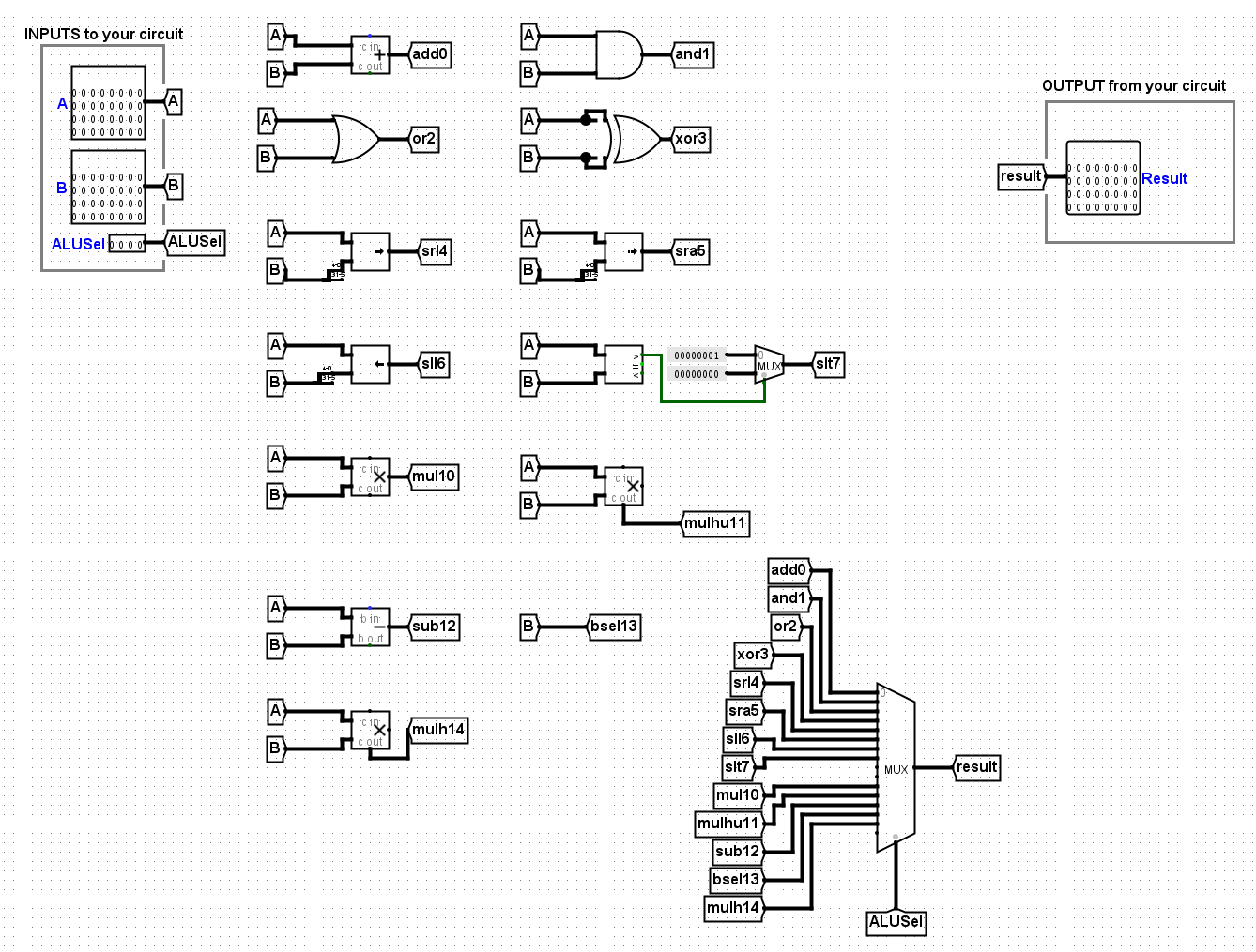
RegFile
正如您在课堂上学到的那样,RISC-V 架构有 32 个寄存器。对于这个项目,我们将实现所有这些。为了帮助调试,我们编写了 regfile 来公开下面指定的 9 个端口。请确保这些 register 的值附加到正确的 outputs。
您的 RegFile 应该能够写入或读取给定 RISC-V 指令中指定的这些寄存器,而不会影响任何其他寄存器。有一个值得注意的例外:即使指令尝试,您的 RegFile 也不应写入 x0。请记住,零寄存器的值应始终为 0x0。您不应在 RegFile 中的任何位置对时钟进行门控:时钟信号应始终直接连接到寄存器的时钟输入,而无需通过任何组合逻辑。
| Register Number | Register Name |
|---|---|
| x0 | x0 |
| x1 | ra |
| x2 | sp |
| x5 | t0 |
| x6 | t1 |
| x7 | t2 |
| x8 | s0 |
| x9 | s1 |
| x10 | a0 |
The register file circuit has six inputs:
| Input Name | Bit Width | Description |
|---|---|---|
| Clock | 1 | Input providing the clock. This signal can be sent into subcircuits or attached directly to the clock inputs of memory units in Logisim, but should not otherwise be gated (i.e., do not invert it, do not “and” it with anything, etc.). |
| RegWEn | 1 | Determines whether data is written to the register file on the next rising edge of the clock. |
| Read Register 1 (rs1) | 5 | Determines which register’s value is sent to the Read Data 1 output, see below. |
| Read Register 2 (rs2) | 5 | Determines which register’s value is sent to the Read Data 2 output, see below. |
| Write Register (rd) | 5 | Determines which register to set to the value of Write Data on the next rising edge of the clock, assuming that RegWEn is a 1. |
| Write Data (wb) | 32 | Determines what data to write to the register identified by the Write Register input on the next rising edge of the clock, assuming that RegWEn is 1. |
The register file also has the following outputs:
| Output Name | Bit Width | Description |
|---|---|---|
| rs1 | 32 | Driven with the value of the register identified by the Read Register 1 input. |
| rs2 | 32 | Driven with the value of the register identified by the Read Register 2 input. |
ra Value |
32 | Always driven with the value of ra (This is a DEBUG/TEST output.) |
sp Value |
32 | Always driven with the value of sp (This is a DEBUG/TEST output.) |
t0 Value |
32 | Always driven with the value of t0 (This is a DEBUG/TEST output.) |
t1 Value |
32 | Always driven with the value of t1 (This is a DEBUG/TEST output.) |
t2 Value |
32 | Always driven with the value of t2 (This is a DEBUG/TEST output.) |
s0 Value |
32 | Always driven with the value of s0 (This is a DEBUG/TEST output.) |
s1 Value |
32 | Always driven with the value of s1 (This is a DEBUG/TEST output.) |
a0 Value |
32 | Always driven with the value of a0 (This is a DEBUG/TEST output.) |
我的实现
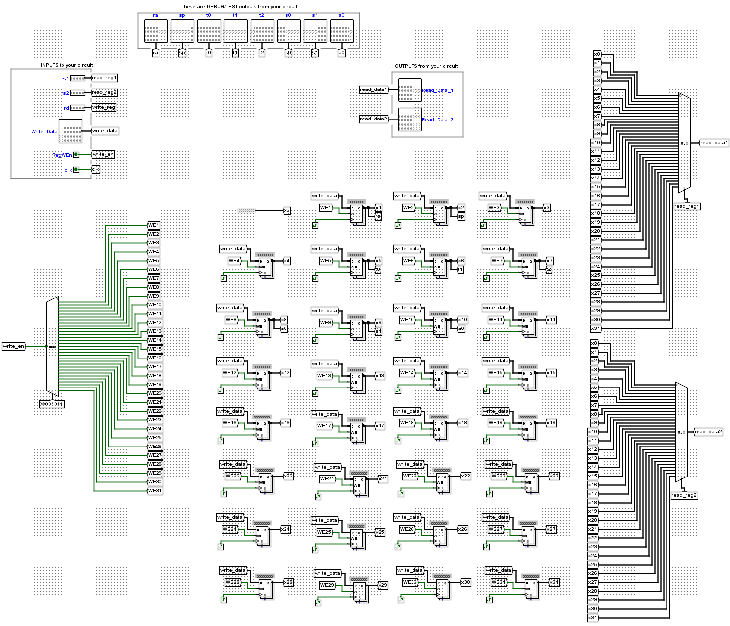
关于 part B
part B 被分为几个细小的任务
Branch Comparator 的实现
| Signal Name | Direction | Bit Width | Description |
|---|---|---|---|
| rs1 | Input | 32 | Value in the first register to be compared |
| rs2 | Input | 32 | Value in the second register to be compared |
| BrUn | Input | 1 | Equal to one when an unsigned comparison is wanted, or zero when a signed comparison is wanted |
| BrEq | Output | 1 | Equal to one if the two values are equal |
| BrLt | Output | 1 | Equal to one if the value in rs1 is less than the value in rs2 |

Imm Generator 的实现
| Signal Name | Direction | Bit Width | Description |
|---|---|---|---|
| inst | Input | 32 | The instruction being executed |
| ImmSel | Input | 3 | Value determining how to reconstruct the immediate |
| imm | Output | 32 | Value of the immediate in the instruction |
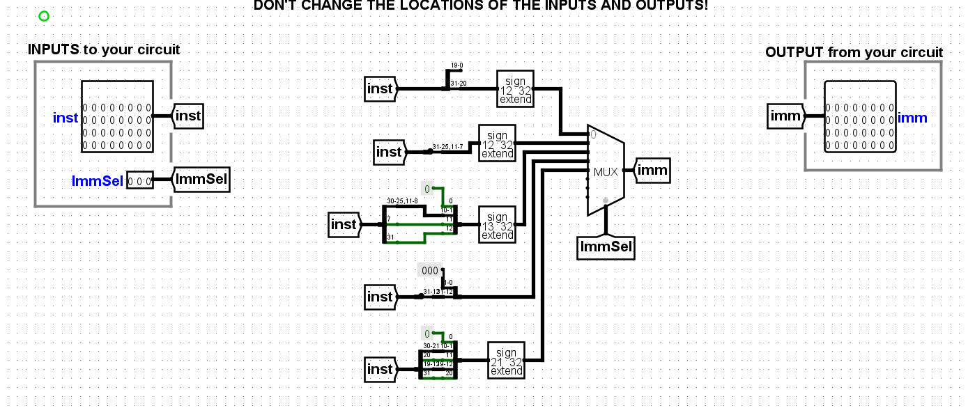
目前我卡在 Control Logic
该文档将重点记录我实现往后的思路
10·21
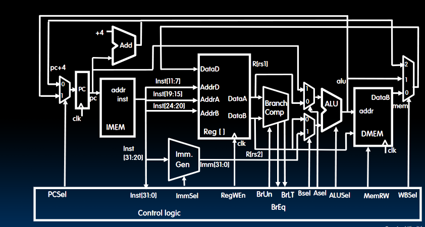
这是 CPU 的 DataPath,目前我在电路模拟中所画的电路图如下:
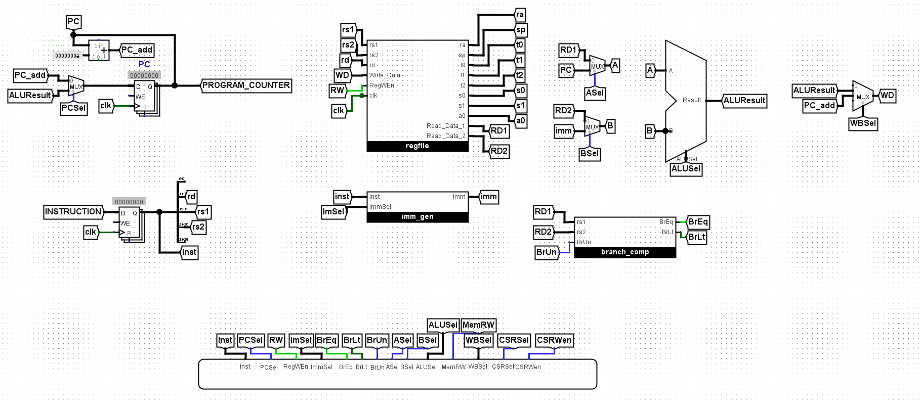
我的 DMEM 还没有体现在这里
指南中推荐的方法有:
- hard-wired control,硬连线控制,如讲座中所述,这通常是 MIPS 和 RISC-V 等 RISC 架构的首选方法。硬连线控制使用 “AND”、“OR” 和 “NOT” 门(以及我们学到的可以从这些门构建的各种组件,如 MUX 和 DEMUX)来产生适当的控制信号。指令解码器接收一条指令并输出该指令的所有控制信号。
- 另一种方法是使用 ROM 控制。处理器实现的每条指令都映射到只读存储器 (ROM) 单元中的地址。ROM 中该地址的 address 是该指令的控制字。地址解码器接收一条指令并输出该指令的控制字地址。这种方法在 Intel 的 x86-64 等 CISC 架构中很常见,并且在现实生活中提供了一些灵活性,因为它可以通过更改 ROM 的内容来重新编程。
我将使用 ROM 控制
关于 ROM 控制
ROM 相关讲座在 Lec20 当中
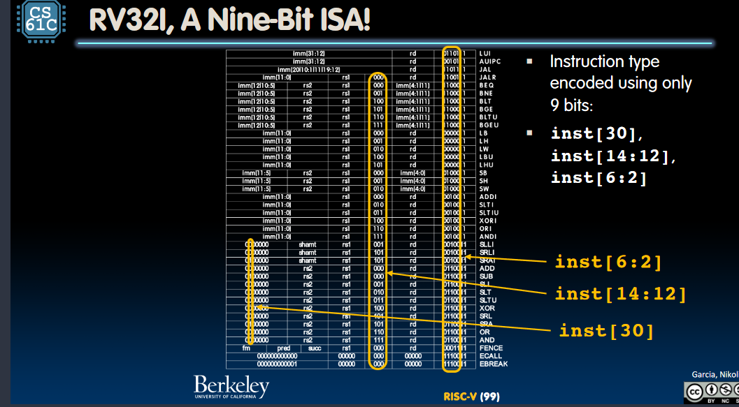
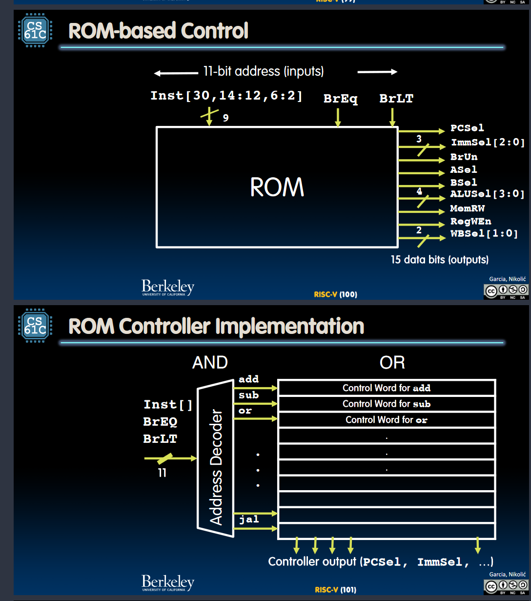
以上是 ROM 的工作原理,以 add 指令为例子
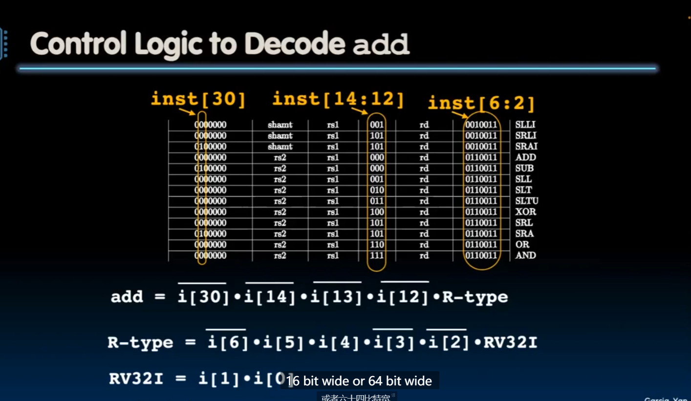
目前资料
ROM Control Logic 表格
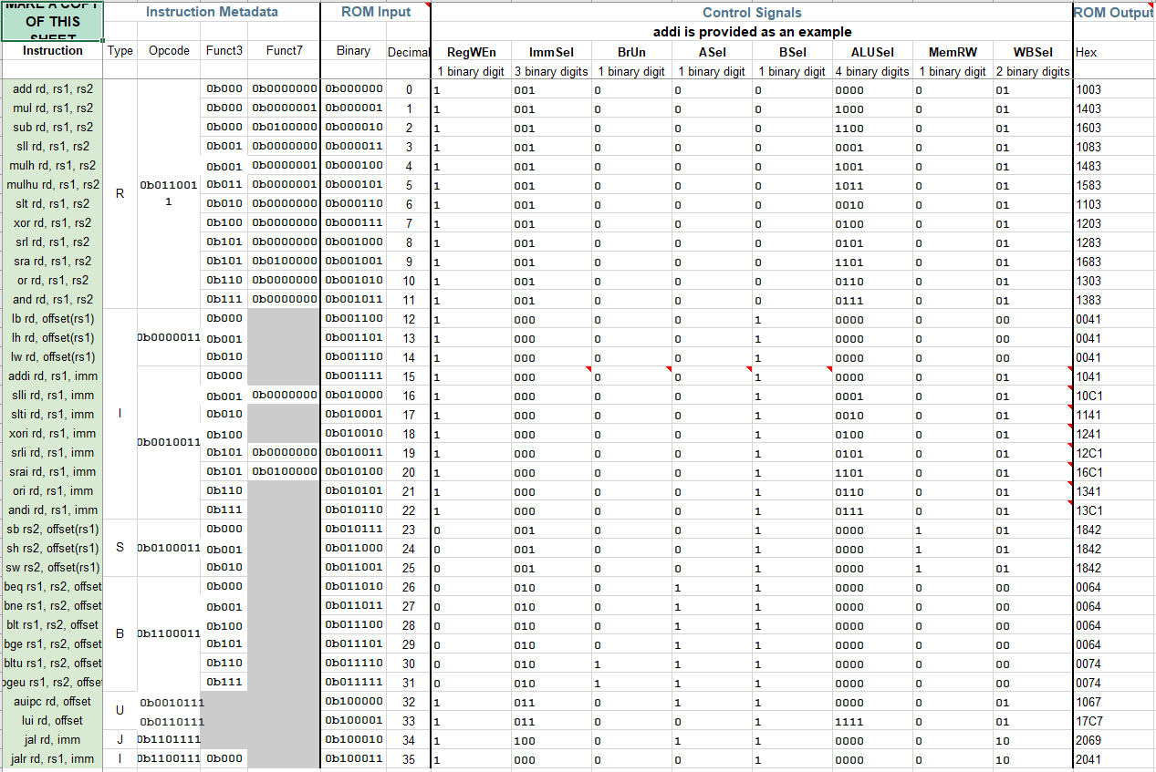
Lec20 的 ppt
明天需要做的事情
完整了解一遍 cpu 数据路径,根据 excel 表格初步确认自己要做什么


